
Structural Integrity by Design: Optimizing Wall Thickness, Perimeters, and Print Orientation for Functional 3D Prints
When producing end-use functional components via fused deposition modeling, relying on generic slicer presets often leads to structural failure under load. While many hobbyists blindly scale infill density to chase strength, advanced additive manufacturing engineering proves that perimeters and wall counts dictate mechanical performance far more than interior lattice structures. Designing robust industrial brackets, mechanical housings, and load-bearing fixtures requires a deep understanding of perimeter geometry, vector loading, and anisotropic stress distribution across layer lines.
Perimeter Count vs. Infill Density: The Structural Hierarchy
Load Distribution in Walls:
Perimeter shells carry the vast majority of tensile, flexural, and torsional loads in a 3D printed component. Increasing perimeter count from two to four adds exponentially more flexural rigidity than jumping from 20% to 80% infill density.
The Myth of Dense Infill:
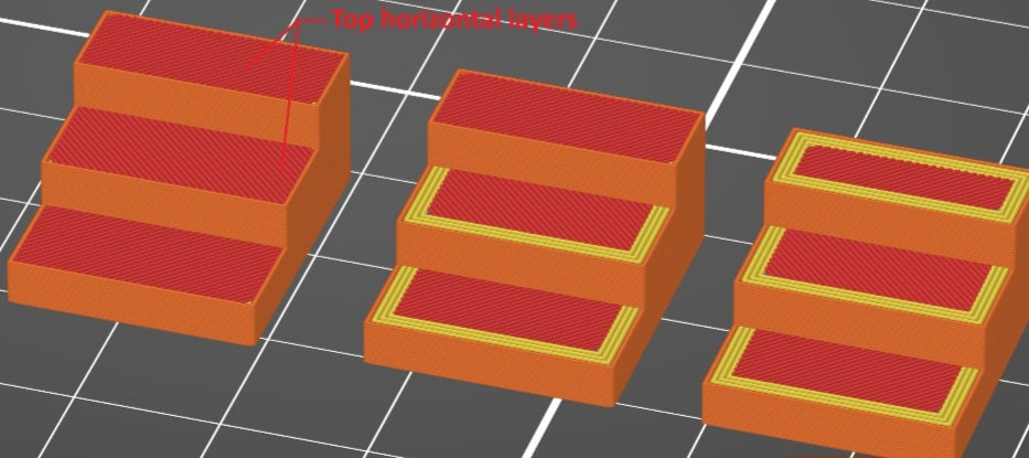
High infill percentages primarily serve to support top solid layers and prevent surface sagging, adding unnecessary material weight and print time without significantly improving primary load-bearing capacity.
Nozzle Width Optimization:
Leveraging wider extrusion line widths—such as running a 0.6 mm or 0.8 mm line width—thickens individual perimeter walls, fusing adjacent passes deeper together to maximize shear resistance.
Anisotropic Dynamics: How Layer Direction Governs Strength
Z-Axis Vulnerability:
Fused deposition modeling prints are inherently anisotropic, meaning their mechanical strength along the Z-axis (interlayer adhesion) is significantly lower than the XY plane. Tensile loads applied perpendicular to layer lines exploit the weakest structural boundary of the part.
Shear Stress and Cleavage:
When a cantilever bracket or pin experiences a bending load, the stress concentrates at the layer interfaces, frequently causing premature delamination long before the base polymer yields.
Strategic Print Orientation for Maximum Mechanical Yield
Aligning Vector Loads with the XY Plane:
Always orient functional parts so that primary tensile and shear forces run parallel to continuous extrusion paths rather than pulling across stacked layers.
Redesigning for Orientation:
If a critical pin or mounting ear is forced to bear load along the Z-axis, split the CAD model and reorient the sub-components to ensure continuous perimeter loops absorb the stress vectors.
Balancing these geometric variables against material inputs and print times allows your workshop to engineer reliable, high-load industrial parts. By prioritizing robust perimeter counts, wider extrusion widths, and strategic part orientation over simple infill adjustments, you eliminate weak points and produce end-use components built for demanding operational environments.
To push component performance even further, advanced workshops often implement multi-material or variable-density perimeter strategies within modern slicers. By assigning different volumetric extrusion rates or increasing wall counts specifically around high-stress fastener holes and mounting bosses—while keeping non-structural core regions lean—you optimize the mass-to-strength ratio without compromising the part's overall mechanical envelope.


