
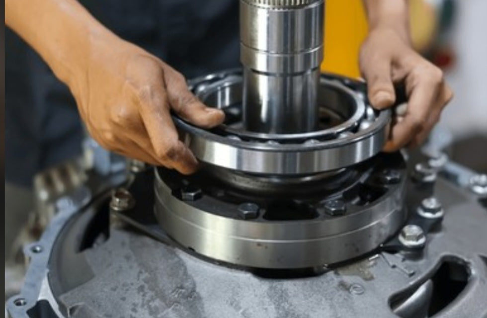
Designing Integrated Bearings and Rolling-Element Assemblies in 3D Printed Parts: Tolerances, Raceway Geometry, and Functional Kinematics
Transitioning from static 3D printed housings to dynamic, moving assemblies requires integrating rotational elements like ball bearings, rollers, or direct-print journals directly into the plastic matrix. Unlike traditional machining where hardened steel or aluminum bearing seats are bored to exacting sub-micron tolerances, fused deposition manufacturing introduces surface roughness, anisotropic layer lines, and minor dimensional drift. Without careful engineering of bearing pockets, interference fits, and raceway clearances, standard commercial bearings will skew under load, and printed sliding journals will permanently lock up. For industrial workshop operations and mechanical designers, mastering how to house or print functional bearings is the key to creating robust gearboxes, hinges, and automated motion systems.
The Mechanics of Bearing Integration in Additive Manufacturing
Press-Fit Pockets and Radial Hoop Stress:
Inserting standard metal shielded bearings into printed plastic pockets requires precise diametric allowance; if the pocket is too tight, the outer race will distort, pinching the internal balls and causing rough, binding rotation.
Direct-Print Captive Bearings and Clearance Gaps:
Designing functional rolling elements (like printed planetary gears or captive ball bearings) directly on the build plate demands strict clearance gaps—typically 0.2 mm to 0.4 mm—to prevent adjacent layers from fusing together during the initial thermal extrusion pass.
Anisotropic Load Distribution:
Bearing housings subjected to radial or axial loads will exploit weak Z-axis layer bonding if the primary vector pulls perpendicular to the layer lines, leading to catastrophic housing delamination under continuous operational stress.
Shop Floor Strategies for Bearing Housings and Direct-Print Mechanics
Designing Solid Perimeters Around Pockets:
Never house a metal bearing in a thin-walled perimeter; program your slicer for at least four to six outer walls and dense internal infill around bearing seats to absorb radial expansion and hoop stresses.
Integrating Chamfered Leads and Retention Lips:
Add a slight 45-degree lead-in chamfer to bearing pockets for smooth press-fit insertion, and design a shallow retention lip or snap-feature to prevent bearings from walking out under axial loads.
Post-Processing and Mechanical Re-reaming:
Use precision reamers or manual scraping on printed journals and direct-print raceways to eliminate staircase friction before final assembly and lubrication.
Mastering bearing integration elevates your 3D printing workflow from static prototyping to complex kinetic manufacturing. By accounting for material elasticity, thermal contraction, and precise mechanical tolerances, your workshop can build reliable, smooth-running assemblies capable of enduring heavy operational cycles.
For ultimate longevity in high-rpm or heavy-load configurations, consider pairing your printed bearing pockets with high-viscosity synthetic greases or solid PTFE dry-film lubricants rather than standard light machine oils. Because engineering thermoplastics possess porous microscopic surface structures, selecting the right lubricant prevents premature surface galling, dampens high-frequency operational harmonics, and significantly reduces frictional heat buildup over extended duty cycles.


