
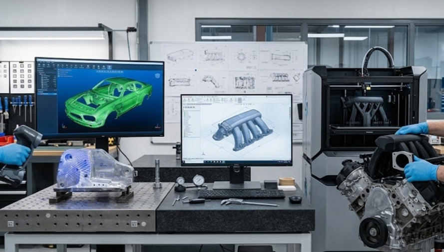
Bridging the gap between a raw point cloud scan and a physical, functional prototype is the true test of any automotive reverse engineering workflow. Acquiring thousands of high-precision spatial data points across a component’s surface is only the first step. To transform that unstructured polygon mesh into a tangible, rapid-prototyped test fit, engineers must convert raw spatial data into clean, editable parametric geometry, design precise mating features, and account for real-world additive manufacturing tolerances.
Skipping key calibration steps during this translation often leads to physical binding, warped bolt patterns, or incorrect offsets against chassis mounting points. Executing a seamless, workshop-proven pipeline turns a digital scan into an exact 3D-printed physical test component that drops into place on the first attempt.
Raw Mesh to Solid Parametric CAD:
Converting tessellated STL surfaces into editable solids requires extracting true mechanical primitives, centerline axes, and feature planes rather than simply auto-surfacing organic shapes.
Accounting for Thermal Plastic Shrinkage:
Additive manufacturing polymers contract as they cool from extrusion temperatures, requiring precise micro-scaling adjustments during slicer setup.
Designing Clearance Tolerances for Mating Interfaces:
Static 3D scan data reflects nominal zero-clearance boundaries, meaning physical test prints require designated gap offsets to slide over factory studs smoothly.
Strategic Slicing and Infill Alignment for Physical Structural Integrity:
Orienting layers and internal lattice density correctly prevents flexible mounting tabs from snapping during trial fitting under bolting torque.
Step-by-Step Workflow: Scan-to-Print Execution Protocol
Transitioning a digitized automotive component into a physical test fit demands a methodical, multi-stage engineering pipeline.
Polygon Mesh Cleanup and Axis Alignment:
Import the raw scan into your CAD reverse engineering suite (such as Geomagic Design X, Fusion 360, or SolidWorks). Clean up stray noise, cap open surface boundaries, and orient the part to a global coordinate system based on primary mounting faces.
Feature Extraction and Parametric Reconstruction:
Extract key mechanical geometries—such as cylinder bores, planar pads, and swept profiles—from the reference mesh. Build fully parametric sketches directly over the scan cross-sections to generate an editable CAD model.
Applying clearance Offsets and Hole Tolerances:
Expand bolt pass-through holes by +0.3 mm to +0.5 mm beyond nominal scan diameter. Add targeted chamfers along leading mating edges to ensure effortless alignment during manual test placement.
Exporting and Slicing Parameter Calibration:
Export the parametric solid as a high-resolution STEP or STL file. Import the geometry into your slicing software, applying a 100.2% to 100.4% horizontal expansion scale factor to counteract filament shrinkage.
Executing the Rapid Physical Print:
Print the prototype using a dimensional-stable material like PETG or Tough PLA, keeping layer heights around 0.2 mm to ensure crisp thread definition and accurate flange flatnesses.
Conducting Physical Vehicle Test Fitment:
Mount the 3D-printed prototype onto the engine bay or chassis mounting points. Check bolt pattern alignment, clearance gaps against adjacent components, and clip engagement before committing to final production tooling.
Managing Additive Manufacturing Tolerances and Fit Dynamics
In addition to CAD accuracy, physical prototype validation depends heavily on printer kinematic fidelity and material behavior. Standard desktop FDM printers inherently introduce minor dimensional variations across the X, Y, and Z axes due to belt tension, nozzle wear, and bed level drift. Running a standardized dimensional test cube calibration prior to sending complex automotive brackets to the print bed guarantees that hole centers and outer boundary dimensions match your CAD file within \pm0.1\text{ mm}.
Translating 3D scan data into a physical, functional test fit closes the loop between virtual metrology and hands-on automotive fabrication. By combining disciplined parametric CAD reconstruction, precise clearance offsets, and calibrated additive manufacturing parameters, custom vehicle parts move from initial digital capture to a perfect workshop fit with complete confidence.


