
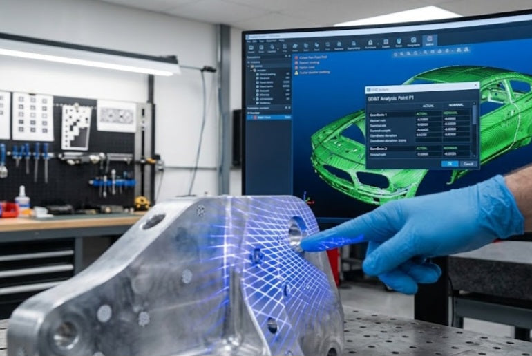
When reverse-engineering an automotive bracket, engine mount, or body panel, capturing the general exterior shape is only half the battle. The ultimate test of a successful 3D scan and CAD reconstruction lies in the dimensional precision of its fastener locations. If a single mounting hole is shifted by even half a millimeter due to scan warping, coordinate misalignment, or mesh distortion, bolts will bind, brackets will crack under pre-load, and custom fabricated parts will fail to fit during final assembly. Validating hole centers and bolt-circle diameters against baseline CAD or physical gauge measurements is a critical quality gate in professional metrology.
Verifying hole positions requires transitioning from raw polygon inspection to advanced GD&T (Geometric Dimensioning and Tolerancing) feature extraction. Let's break down the technical workflow for isolating, extracting, and verifying mounting-hole positions from a scanned car part.
The Challenge of Polygonal Hole Edges:
Scanned holes often feature faceted mesh edges, surface noise, and partial occlusion from bolt heads, requiring algorithmic cylinder fitting rather than simple vertex picking.
Datum Reference Frames (DRF):
Establishing a true primary, secondary, and tertiary coordinate system ensures that hole positions are measured relative to actual physical locating pins and mating faces.
Axis Vector Deviation:
Evaluating not just the X, Y, Z center coordinate of a hole, but its exact angular vector to detect any tilt or bore skew.
Fit Simulation via Tolerance Zones:
Using metrology inspection software to run maximum material condition (MMC) checks and coaxiality tolerances on critical fastener patterns.
Step-by-Step Hole Position Verification
Protocol
Validating mounting-hole accuracy on a scanned automotive component requires a disciplined sequence of feature extraction and spatial analysis.
Importing and Aligning the Scan Mesh:
Import your clean STL mesh into metrology inspection software (such as Geomagic Control X, PolyWorks, or GOM Inspect). Align the scan to the master CAD model using an iterative closest point (ICP) or a 3-2-1 datum alignment based on primary mounting pads.
Cylinder Feature Extraction:
Select the inner cylindrical surface of the mounting hole. Instruct the software to fit a least-squares cylinder primitive to the polygonal data, which mathematically determines the true center axis and diameter.
Establishing Nominal Datums:
Define primary, secondary, and tertiary datums using the component's factory-machined locating surfaces, pilot pins, or reference holes.
Running Dimensional Comparison Analysis:
Generate 3D deviation callouts comparing the extracted scan hole centers against the nominal CAD coordinates. Set up color-coded tolerance maps to instantly flag out-of-spec deviations.
Analyzing Angular Skew and Bore Alignment:
Check the vector orientation of each hole axis to ensure fasteners enter perpendicularly without cross-threading or creating side loads against mating brackets.
Exporting Inspection Reports:
Compile the coordinate deviation data, diameter variances, and graphical GD&T callouts into a comprehensive PDF inspection report for quality sign-off.
Advanced Tolerance Stack-Up and Fixture Simulation
Beyond individual hole coordinates, complex automotive assemblies require accounting for cumulative tolerance stack-up. When multiple mounting holes are distributed across a flexible plastic or stamped steel bracket, a minor localized error in one hole can compound across the span, preventing bolts from aligning simultaneously. Advanced metrology software allows engineers to simulate virtual assembly conditions—applying boundary constraints to see whether a part will drop onto fixed studs without elastic deformation or stressing the surrounding structure.
Checking mounting-hole positions in a car-part scan bridges the gap between raw digital data and reliable mechanical performance. By mastering least-squares cylinder fitting, datum reference alignment, and vector deviation analysis, you guarantee that every reverse-engineered bracket or panel bolts up perfectly on the first try.
Automating hole location inspection marks a major shift toward high-throughput quality control in modern fabrication workshops. By feeding extracted hole vectors directly into downstream parametric modeling tools or robotic drill paths, you establish a seamless digital thread that connects inspection data straight to CNC machining centers. This level of automated verification eliminates human manual measuring error entirely, allowing custom automotive components to progress from a raw 3D scan to a fully validated, production-ready manufacturing file in a fraction of the traditional turnaround time.


