
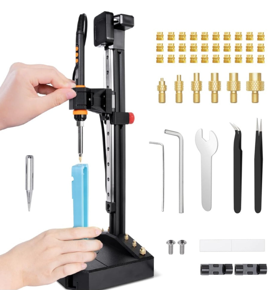
One of the most transformative upgrades you can make to your 3D printing workflow is moving away from threading screws directly into plastic holes. While direct-threading works for low-stress prototypes, it strips easily, wears out after a few assembly cycles, and lacks the clamping force required for serious mechanical assemblies.
Enter brass heat-set inserts. By melting a threaded brass insert directly into a custom-designed pocket using a soldering iron, you gain steel-grade, metal-on-metal fastening power inside your thermoplastic parts. However, simply dropping an insert into a standard hole will lead to cracked prints, crooked threads, or pulled-out fasteners. Designing specifically for heat-set inserts requires strict adherence to geometry, pocket depth, and wall thickness rules.
In this comprehensive guide, we will break down the engineering principles behind brass heat-set inserts and show you how to design foolproof CAD pockets for maximum pull-out and torque resistance.
Understanding the Anatomy of a Heat-Set Insert
Before sketching your CAD pocket, it helps to understand how a standard brass insert (such as a McMaster-Carr style tapered insert) anchors into plastic.
The Knurled Barrel:
The outer body features diagonal or diamond-shaped knurling. When heated, the brass melts its way into the surrounding plastic; as the plastic cools, it flows tightly into the grooves, locking the insert against rotation and pull-out forces.
The Pilot and Taper:
Most inserts feature a slight outer taper at the bottom, which acts as a self-centering guide when pressed into your printed hole.
The Internal Threads:
Ranging from M2 up to M6 or larger, these clean machine threads accept standard metric machine screws with incredible durability.
Calculating the Optimal Hole Diameter (The Boss Dimension)
Getting your pre-print hole diameter right in CAD is critical. If the hole is too wide, the insert will sit crooked and slip when tightened; if it is too narrow, the plastic will displace too aggressively and crack your part.
The Golden Rule:
The hole diameter should match the outer diameter of the insert's pilot section (just above the taper, but below the knurling peaks).
Standard Sizing Reference (for common M3 and M4 inserts):
M3 Insert:
Typically requires a hole diameter around 4.0mm to 4.2mm.
M4 Insert:
Typically requires a hole diameter around 5.5mm to 5.7mm.
M5 Insert:
Typically requires a hole diameter around 6.8mm to 7.0mm.
Pro Tip:
Always print a small test block for a new spool of filament or brand of inserts to dial in your printer's exact shrinkage and extrusion tolerances.
Designing Adequate Wall Thickness Around the Insert
When you press a hot brass insert into plastic, it displaces a significant amount of material outward. If your surrounding walls are too thin, the internal stress will cause the plastic to bulge, distort, or fracture entirely.
Minimum Wall Rule:
Ensure you have at least 1.5mm to 2.0mm of solid plastic wall thickness surrounding every side of the insert.
Building Bosses:
If your insert is placed on a flat, thin panel, do not just punch a hole in the surface. Design a raised cylindrical boss around the hole to provide the necessary structural meat and hoop strength to withstand the expansion forces of installation and screw torque.
Pocket Depth and Clearance (Avoiding Bottom-Out)
A common beginner mistake is designing a hole that is too shallow, forcing the hot insert to bottom out before it is flush with the surface.
Depth Matching:
Make your CAD hole depth slightly deeper (by about 0.5mm to 1.0mm) than the overall length of the insert. This ensures the top flange or rim of the insert can sit perfectly flush with your part surface without slamming into a solid plastic floor.
The Underside Void:
If a screw is longer than your insert, ensure there is open air or a clearance channel beneath the insert so the screw tip has room to pass through rather than pushing the insert right back out of its pocket.
Slicer Settings for Maximum Insert Holding Power
Your CAD design is only half the battle; how your slicer structures the plastic around the hole dictates ultimate mechanical strength.
Perimeters Over Infill:
Inserts anchor almost entirely into the perimeter walls (walls/shells) rather than sparse internal infill. Set your slicer to use at least 3 to 4 outer perimeters (walls) so the brass knurling bites into solid, continuous loops of plastic instead of hollow grid patterns.
Solid Layers:
Ensure your design incorporates enough solid top and bottom layers so the pocket does not accidentally open up into a hollow infill cavity mid-depth.
Mastering heat-set inserts transforms your 3D printed objects from brittle plastic mockups into professional, field-serviceable assemblies that rival injection-molded hardware.
By engineering dedicated structural bosses, maintaining strict perimeter counts, and accounting for the thermal dynamics of brass installation, you eliminate the risk of stripped threads and catastrophic joint failure.
Implementing these deliberate design rules ensures your mechanical fasteners stay locked under heavy vibration and repeated disassembly cycles.


