
One of the most satisfying milestones in 3D printing is moving beyond standalone aesthetic models and creating fully functional mechanical assemblies where parts screw together seamlessly.
Whether you are designing custom bottle caps, multi-part threaded enclosures, or adjustable mechanical jigs, integrating working threads directly into your thermoplastics opens up a massive realm of engineering possibilities.
However, trying to thread a printed bolt into a printed nut right off the build plate often leads to frustrating friction, locked-up joints, or completely stripped teeth.
Because 3D printers lay down molten plastic in discrete layers and horizontal vectors, standard CAD thread profiles behave very differently in the physical world than they do on your computer screen.
In this comprehensive guide, we will break down the geometry, tolerances, and slicer strategies required to print smooth, durable, and fully functional screw fits on your desktop 3D printer.
Choosing the Right Thread Profile (Triangle vs. Trapezoid)
Not all thread profiles are created equal when it comes to additive manufacturing. Choosing the correct thread geometry determines how easily your parts will mate.
The Metric V-Thread (Standard):
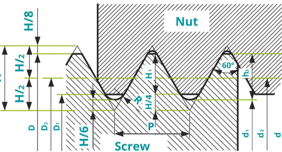
Standard ISO metric threads (like M3, M5, or M8) feature sharp 60^\circ triangular peaks. While they work exceptionally well for metal fasteners, they can be difficult to print cleanly at small scales because the tiny peaks lack structural support and tend to droop or fuse together.
The Trapezoidal or Acme Thread:
For larger custom 3D printed threads, utilizing a trapezoidal or square profile (similar to lead screws) is often much more successful. These profiles feature flat peaks and troughs, making them significantly easier for an extrusion nozzle to bridge and reproduce without sagging.
The Tolerance Gap: Why Clearance is Non-Negotiable
If you model a mating screw and nut with exact mathematical dimensions (a 0mm tolerance fit), friction and layer lines will lock them together permanently.
The Air Gap Factor:
Plastic is not perfectly smooth; microscopic layer ridges and slight over-extrusion create high-friction contact points. To get a smooth screw fit, you must build a microscopic clearance gap into your CAD design.
Designing Tolerances:
As a general rule of thumb for standard FDM printers, apply an offset of at least 0.2mm to 0.4mm between the male and female threads (meaning you expand the internal thread diameter or shrink the external thread diameter slightly). This gives the mating parts enough breathing room to clear micro-imperfections without introducing excessive wobble.
Orientation Matters: Printing Vertical vs. Horizontal
How you orient your threaded components on the build plate dictates whether the threads will survive the assembly process.
Printing Vertically (Recommended):
Printing bolts and nuts standing upright along the Z-axis ensures the circular geometry remains round. However, this places shear stress across the layer lines, meaning the threads could snap off under high torque if your layer adhesion is weak.
Printing Horizontally:
Printing threads lying flat on their side preserves the tensile strength of the part along the thread path, but the bottom half of the thread will experience minor sagging due to overhangs. If you print horizontally, you must rely heavily on clean bridging capabilities and good cooling.
Slicer Strategies for Crisp, High-Resolution Threads
Your hardware and CAD design are only half the battle; your slicer settings control how accurately those microscopic thread faces are translated into plastic.
Drop Your Layer Height:
Threads rely entirely on high resolution. Printing at a standard 0.28mm layer height will result in chunky, stair-stepped thread faces that grind against each other. Drop your layer height to 0.12mm or 0.16mm to create smooth, tightly stacked steps that mimic true helical ramps.
Slow Down the Perimeter Speed:
Printing outer perimeters at a blistering speed on small radii causes the nozzle to overshoot corners and round off delicate thread edges. Cut your outer wall speed in half (e.g., 30mm/s to 40mm/s) to ensure crisp, accurate thread geometry.
Post-Processing and Mechanical Break-In
Even with perfect settings, freshly printed threads can benefit from a little assistance during their very first mating cycle.
The Initial Run-In:
Do not force a tight printed screw with a wrench on the first try. Coat the threads with a tiny drop of mineral oil, candle wax, or dry PTFE lubricant, and gently screw and unscrew the parts back and forth. This acts like a mechanical lap, smoothing out any microscopic high points in the plastic layers.
Tap and Die Clean-Up:
For heavy-duty functional prints using standard metric thread sizes, running a standard steel tap through the printed nut or a die over a printed bolt will instantly clean out stray strings and deliver buttery-smooth action.
Mastering 3D printed threads transforms your fabrication workflow by eliminating the need for external hardware on custom enclosures and interlocking mechanisms.
By understanding thread geometry, engineering mandatory clearance gaps, optimizing print orientation, utilizing fine layer heights, and properly breaking in your mechanical fits, you can produce reliable, smooth-operating screw assemblies straight off your print bed.


