
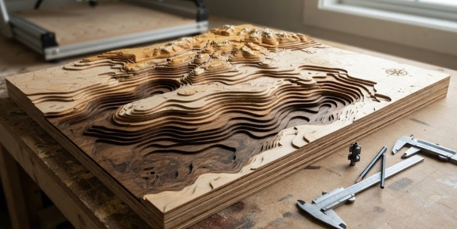
Few decor projects capture a workshop's true technical capabilities quite like a multi-layered topographic wooden map. Whether you are charting coastal bathymetry, mountain contour lines, or custom regional street layouts, translating flat vector data into a stunning, three-dimensional physical relief model transforms raw sheet goods into heirloom-quality art. While laser cutters are often used for quick vector stacking, they leave dark, scorched burnt edges that require intensive hand-sanding. A desktop CNC router, by contrast, lets you mill clean, pristine pockets, contours, and elevation steps with authentic wood-grain aesthetics.
Creating a multi-layered map requires careful CAD/CAM preparation, smart material selection, and precise glue-up strategies to ensure every elevation tier fits together without alignment gaps. Let's explore how to design, machine, and assemble a professional topographic map using your desktop CNC router.
The Power of Elevation Layers:
Breaking a 3D landscape into distinct 2D vector slices (elevation bands) allows you to use different wood species or stains for each tier, creating rich visual contrast.
Material Thickness Management:
Using thin sheet goods—such as 3mm or 6mm Baltic birch plywood or MDF—makes it easy to step elevations without creating an overly bulky finished piece.
The Scribing and Vector Challenge:
Inverting and nesting your vector lines properly in your CAM software prevents tear-out and ensures water bodies or recessed valleys sit flush beneath upper landmasses.
Registration and Alignment:
Because multiple layers must align perfectly during assembly, incorporating mechanical registration dowel holes into your G-code is essential.
Step-by-Step Layering Protocol
Building a precision topographic map on a desktop CNC router requires a disciplined workflow from digital design to final lamination.
Vector Preparation and Slicing:
Import your elevation contour data or DEM (Digital Elevation Model) files into your CAD software. Slice the model into distinct flat horizontal planes matching your stock thickness (e.g., three 3mm layers for lowlands, 6mm layers for hills). Ensure every layer includes common outer boundary alignment marks or corner registration holes.
Selecting the Right Bits:
Use a 1/8-inch up-cut spiral bit for roughing out large interior landmass pockets and exterior profiles. Switch to a 1/16-inch down-cut bit for fine details, rivers, or intricate coastline features to prevent top-veneer splintering.
Workholding and Registration:
Screw or tape your plywood sheet down securely to the spoil board. Drill your registration pin holes first into the spoil board through the stock, and insert tight-fitting dowel pins to lock each subsequent layer in exact physical alignment during multi-sheet operations.
Machining and Pocketing:
Run your toolpaths layer by layer. For water or valley beds, program pocket toolpaths that drop down half a step so upper layers nest cleanly into the recessed channels below them.
Finishing and Staining Individual Tiers:
Sand each layer thoroughly before assembly. To make the topographic steps pop, apply different wood stains or clear sealers to alternating layers—such as a dark walnut stain for deep water channels and a natural honey finish for high plateaus.
Lamination and Clamping:
Use a thin, even coat of wood glue across the layers. Drop the sheets over your alignment dowels to guarantee zero shifting, and clamp the entire assembly under uniform pressure until fully cured.
Fabricating a layered wooden map on a desktop CNC router bridges advanced digital design with classic woodworking craftsmanship. By leveraging precise multi-tier vector slicing, clean bit geometry, and smart dowel alignment, you can transform flat sheet materials into breathtaking, tactile topographical art pieces.


