
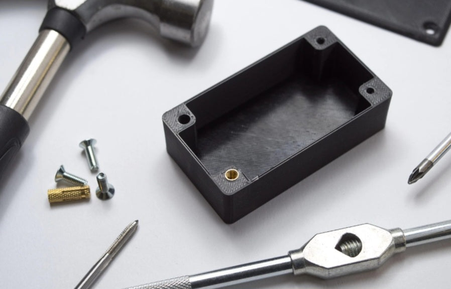
One of the most frustrating discoveries for any 3D printing enthusiast or mechanical designer is finishing a print, grabbing a bolt, nut, or bearing that measured precisely 10mm in CAD, only to find it refuses to fit into the printed hole.
Whether you are designing mechanical assemblies, snap-fit components, or functional brackets, dimensional inaccuracy can throw off an entire project.
If you constantly find yourself drilling out holes or forcing screws into tight slots, you are not alone. Hole shrinkage is one of the most common hurdles in 3D printing.
Below is a comprehensive breakdown of why your 3D printed holes are coming out too small, the physics behind the phenomenon, and actionable solutions to achieve perfect dimensional accuracy every time.
The Physics of Polymer Shrinkage (Thermal Contraction)
The primary culprit behind undersized holes is how thermoplastics behave when heated and cooled.
The Cooling Effect:
When plastic is extruded from the nozzle, it is hot and expanded. As it cools down on the build plate, it contracts.
Inward Pulling Forces:
As each successive perimeter line of a hole is printed in a circular motion, the cooling plastic pulls inward toward the center of the geometry. This cumulative inward contraction reduces the overall diameter of the hole, making it smaller than your CAD model specified.
Material Variance:
Different filaments shrink at different rates. Standard PLA shrinks very little, making it relatively forgiving, whereas engineering polymers like ABS, Nylon, and Polycarbonate experience severe thermal contraction and are notorious for shrinking holes.
Perimeter and Wall Line Interactions (Extrusion Width)
Slicers translate your digital 3D model into toolpaths based on your nozzle size and extrusion width settings. How your slicer handles inner perimeters plays a massive role in hole sizing.
Default Slicer Overlaps:
Most slicers prioritize outer dimensions, but inner perimeters (walls) are calculated based on a set line width (e.g., 0.42mm or 0.45mm for a 0.4mm nozzle).
Rounding Errors:
If your hole diameter does not divide evenly into your line width or nozzle size, the slicer algorithm will often round up or down, frequently resulting in the inner wall shifting slightly inward and choking the opening.
The "Overhang" Effect on Small Radii
Printing a true circle horizontally in 3D space means the top half of the hole is technically printing on thin air (an overhang).
Drooping Filament:
As the nozzle bridges across the top curve of a horizontal hole, the molten plastic tends to sag slightly downward into the void.
The Result:
Instead of a crisp, perfectly round circle, the top of the hole sags inward, leaving a flattened or restricted top edge that blocks inserted fasteners.
How to Fix Undersized Holes (Actionable Solutions)
You do not have to live with poorly fitting hardware. Here are the best ways to correct and prevent undersized holes:
Design Oversized Holes in CAD
If you are designing the parts yourself, the easiest fix is to build tolerance directly into your CAD model.
For small holes (under 10mm), add roughly 0.2mm to 0.4mm to the overall diameter depending on your material and printer calibration.
For tight-fit press-fit bearings, print a test ring first to find your specific machine's offset.
Use Horizontal Expansion Settings in Your Slicer
Modern slicers (like Cura and PrusaSlicer) feature a setting called Horizontal Expansion or Hole Horizontal Expansion.
This setting allows you to globally or selectively shrink or expand outer and inner contours. Applying a tiny negative or positive horizontal expansion specifically to holes compensates for inward shrinkage without throwing off your outer part dimensions.
Switch to Vertical Hole Printing (Orientation)
If possible, reorient your model on the build plate so the hole runs vertically (perpendicular to the bed) rather than horizontally.
Printing a hole vertically means the printer draws concentric circles layer by layer, completely eliminating the top-arch sagging issue and resulting in significantly rounder, more accurate dimensions.
Post-Processing: Reaming and Drilling
For high-precision mechanical assemblies where clearance must be exact:
Design your holes slightly undersized on purpose, and use a hand reamer, twist drill bit, or tap to clean them out post-print. This clears away inner bead irregularities and guarantees a flawless mechanical fit.


