
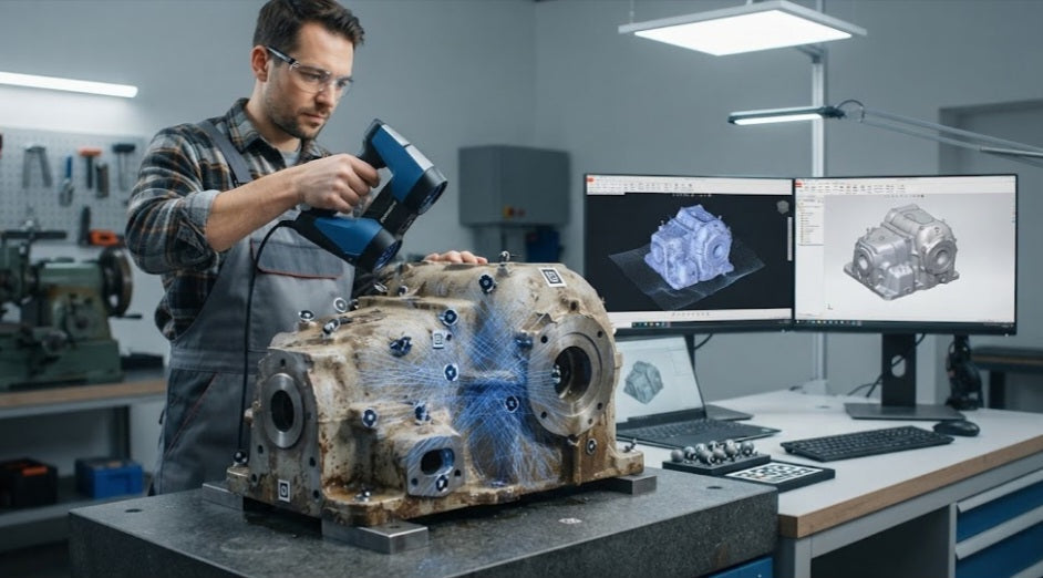
When working with vintage machinery, legacy industrial equipment, or broken cast-iron engine blocks, engineers frequently face a daunting challenge: the original 2D blueprints are long lost, manual caliper measurements are hopelessly inaccurate across complex organic fillets, and replacement parts simply do not exist. Transitioning a weathered, greasy, sand-cast metal component into a pristine parametric CAD model requires optical metrology and reverse engineering. However, old machine castings are notorious for their rough, light-absorbing porous surfaces, sand-cast texture variations, and decades of accumulated oil varnish.
Capturing these heavy industrial components requires a disciplined workflow that bridges raw laser scanning data with high-end solid modeling. Let's break down the step-by-step protocol required to digitize an old machine casting and prepare it for modern CAD reconstruction.
Conquering Casting Texture:
Sand-cast surfaces feature micro-roughness that scatters structured light, requiring specific exposure tuning to avoid point-cloud noise.
Managing Legacy Wear and Tear:
Differentiating between intentional design geometry and decades of mechanical wear, scoring, or corrosion during the CAD modeling phase.
Hybrid Alignment Strategies:
Using datum planes, bored bearing centerlines, and machined mounting faces to establish a true engineering coordinate system.
From Mesh to Parametric Solid:
Bridging organic polygon meshes with precise feature-based CAD modeling using section curves and surface lofting.
Step-by-Step Casting Digitization Protocol
Transforming an industrial relic into clean parametric CAD demands a systematic approach from workshop prep to final solid modeling.
Deep Degreasing and Surface Prep:
Thoroughly hot-tank or chemically degrease the old casting to remove decades of oil, grease, and grime that distort optical readings. If the bare iron or aluminum is highly reflective, apply a thin vanishing scanning spray.
Establishing Global Reference Frameworks:
Place magnetic or adhesive tracking targets around the casting fixture. For large engine blocks or gear housings, use photogrammetry scaling bars to lock down global dimensional accuracy across long spans.
Executing Multi-Pass Laser Scans:
Sweep the casting using high-density blue laser lines. Capture the rough exterior structural walls first, then transition to fine-line mode for machined mating surfaces, threaded bolt holes, and bearing seats.
Point Cloud Cleanup and Mesh Optimization:
Import the raw scan data into reverse engineering software. Remove stray environmental noise, fill minor casting voids, and export a clean, watertight polygonal STL mesh.
Cross-Sectional Slice Analysis:
Slice the mesh along major axes to generate 2D sketch curves that reveal internal wall thicknesses, core shifts, and draft angles inherent to traditional casting.
Parametric CAD Reconstruction:
Build your new parametric model over the mesh using hybrid modeling—recreating precision-machined holes and faces exact, while lofting organic exterior casting walls to match the original form.
Advanced Material Density and Thermal Stability
Surface cleanup and point-cloud alignment, scanning heavy cast-iron or steel machinery involves managing thermal mass equilibrium. Large metal castings act as massive thermal batteries; if brought from a cold outdoor yard into a climate-controlled metrology lab, they can take hours to stabilize thermally. As the heavy casting slowly warms up to room temperature, micro-expansion occurs across its structure, introducing dimensional drift during extended scanning sessions. Allowing the component to acclimate overnight in the workspace ensures absolute volumetric stability before you capture your master baseline scan.
Scanning an old machine casting before rebuilding its CAD model bridges the gap between historical industrial heritage and modern manufacturing. By mastering surface preparation, global target referencing, and hybrid parametric modeling, you can resurrect obsolete machinery with absolute engineering precision.


