
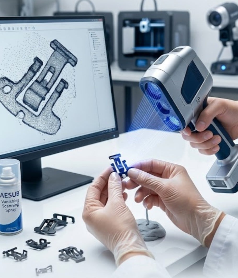
Thin plastic clips (like automotive interior trim clips, cable holders, or retaining tabs) pose a unique challenge in 3D scanning. Because they are flexible, lightweight, and often dark or reflective, applying pressure or standard preparation can physically distort or bend them, leading to an inaccurate scan.
Here is how to get a high-accuracy 3D scan without warping the part:
Key Challenges & Why They Bend
Pressure from Clamping:
Standard vice jaws or heavy clamps easily press into thin plastic, flexing the clip out of its natural shape.
3D Scanning Spray Weight or Heat:
Heat from high-powered light/laser scanners or heavy liquid sprays can temporarily soften thin walls.
Translucency & Reflection:
Many clips are made of black nylon, polypropylene, or smooth ABS, which absorb or refract scanner light without proper spray.
Step-by-Step Scanning Process
Low-Pressure Mounting & Support
Use Pin Vices or Clay:
Mount the clip using a tiny dab of non-staining mounting putty (tack) or a delicate PCB holder at a non-critical point (like an end tab).
Avoid Hard Clamps:
Never use heavy spring clamps or metal vice grips directly on thin walls.
Backing Support:
If the clip is exceptionally thin or flimsy, support the reverse side with soft dental wax or removable silicone putty that doesn't push the plastic out of alignment.
Surface Preparation (Without Heat or Pressure)
Sublimating/Vanishing Spray:
Use a vanishing 3D scanning spray (like AESUB Blue or Orange). It applies a thin, uniform matte coat and completely evaporates on its own within a few hours, eliminating the need to wash or wipe down delicate tabs.
Light Coats Only:
Apply a light, quick pass from 20–30 cm away to avoid liquid weight build-up.
Alignment & Tracking Setup
Turntable Method:
Place the mounted clip on a high-precision turntable with coded targets placed around the table rather than directly on the clip.
Background Contrast:
Use a matte white or black background plate depending on your scanner's light source to ensure high-contrast edge recognition without overexposing thin walls.
Post-Processing & Mesh Cleaning
Trim Excess Fixturing:
Easily crop out the putty or pin support in your scanning software (e.g., Shining 3D, AESUB, or Geomagic).
Thin-Wall Mesh Extraction:
Use surface-thickening or cross-section analysis tools in CAD to verify that the wall thickness in the scan matches physical measurements (caliper check) before sending to production.
Utilizing Non-Contact Optical Metrology and CAD Calibration
When scanning ultra-flexible clips, standard desktop 3D scanners can sometimes pick up slight ambient vibrations or micro-movements, causing digital distortion along narrow clip ridges. To prevent this, using an optical blue-light or high-resolution laser scanner paired with fixed reference points around the fixture—rather than directly on the flexible part—allows the software to lock onto the coordinate system without relying on the physical geometry of the clip itself. Once captured, cross-referencing critical contact points against high-accuracy digital calliper measurements ensures that any remaining micro-flex during scanning is manually recalibrated in your reverse-engineering software before sending the model to print.
3D scanning thin, delicate plastic clips doesn't have to result in warped models or inaccurate replacement parts. By eliminating mechanical clamping pressure, using self-evaporating matte sprays, optimizing ambient light settings, and verifying dimensions with digital callipers, you can reliably capture perfect 3D geometry every single time. With these professional scanning practices, your reverse-engineered clips and replacement parts will snap into place with factory-grade precision.


